
The finishing of accessories: a must in the fashion industry

The finishing of accessories: a must in the fashion industry

a speech by Giulio Bevilacqua

Fashion and the electroplating business. Two apparently distant worlds linked by a technical dialogue that aims at getting things done: fashion brands on the one hand, and finishing “suppliers” on the other. The challenge: to build a business meeting point between strategic sectors that are tendentially little inclined to cross-contaminate and communicate in order to create a new way of thinking about luxury finishings.

A dialogue which inquisitive observation, together with 50 years’ experience, has led to three main aspects.

Aesthetics and fashion, or rather, linking electroplating finishing to the aesthetic value of the finished product. In the past, fashion, leather and footwear accessories were merely thought of as functional elements. Now, also due to the technical finishing skills, they are necessary and indispensable components, often even a distinctive element.

But how is it done? By studying the balance between shape, volume and finishing; by constant dialogue with the clientele; by analysing the input of the people employed in production and all by really listening closely to the surrounding world.

Research and innovation which means putting the experience gained and consolidated in the jewellery world with the biggest luxury brands at the disposal of the fashion supply chain. This translates into a constant experimentation of new processing techniques and research into global trends. One cannot stop at producing finishings with maniacal skill; the commitment, in any sector, is to be one step ahead in order to be able to offer the customers unique and distinctive fashion solutions.

Galvanic plating and sustainability… not a contradiction in terms but a feasible alliance. In times gone by, deciding the company’s environmental sustainability would not have been an option. On the contrary, the fact that it should develop and grow hand in hand with the company has turned out to be a natural choice, certainly not one dictated by legal obligations that did not exist at that time. Changing the idea, not only in the facts, but also in the collective imagination, that an electroplating company could be a sustainable company was a challenge that has become a concrete fact. Over the years, processing techniques, attention to the environmental context in the broad sense, as well as the more fragile contexts of the surrounding territory, have led to certifications, awards and recognitions that certify a virtuous “best practice” route at an organizational, managerial and production level in terms of sustainability.

These are the three pieces of a complex and articulate puzzle in which the various souls of savoir faire converge. A know-how that passionately moves towards creating and offering the fashion supply chain a replicable, recognized and recognizable product in processing, design, relations and service terms.

DOWNLOAD PDF


Continue reading

Galvanica per il settore moda: un caso studio

Galvanica per il settore moda: un caso studio

una relazione di Giulio Bevilacqua

Moda e azienda galvanica. Apparentemente due mondi lontani legati da un dialogo tecnico del fare: da un lato i brand della moda dall’altro i “fornitori” di finiture. La sfida: costruire un incontro d’impresa tra settori strategici poco inclini alla contaminazione e al confronto per creare un nuovo modello di intendere la finitura nel contesto del lusso.

Un dialogo che un’osservazione curiosa, unita ad un’esperienza di 50 anni, permette di ricondurre a tre principali aspetti.

Estetica e moda, ovvero legare anche la finitura galvanica al valore estetico del prodotto finito; l’accessorio della moda, della pelletteria e della calzatura, in passato considerato mero elemento funzionale assurge oggi, anche grazie all’abilità tecnica della finitura, a componente necessaria e imprescindibile, a volte esso stesso elemento distintivo.

Ma come fare? Studio degli equilibri tra forma, volume e finitura; dialogo costante con la clientela; analisi degli input provenienti dal personale impegnato nella produzione, il tutto permeato da un ascolto autentico e profondo del mondo circostante.

Ricerca e innovazione che significa mettere al servizio della filiera della moda un’esperienza nata con il mondo orafo e consolidatasi successivamente con i maggiori brand del lusso. Ciò si traduce in una sperimentazione continua di nuove tecniche di lavorazione e di studio delle tendenze a livello globale. Non ci si deve accontentare di eseguire con abilità maniacale una finitura; l’impegno, in qualsiasi settore, è giocare d’anticipo per proporre soluzioni-moda uniche ed identitarie per i clienti.

Galvanica e sostenibilità… non un ossimoro ma un’alleanza possibile. In tempi non sospetti decidere che la sostenibilità ambientale dell’azienda non sarebbe stata un optional, al contrario, che doveva svilupparsi e crescere di pari passo con essa, si è rivelata una scelta naturale, sicuramente non dettata da obblighi normativi allora inesistenti. Modificare, non soltanto nei fatti ma soprattutto nell’immaginario collettivo, l’idea che un’azienda galvanica potesse essere un’azienda sostenibile è stata una sfida che si è tradotta in azioni concrete: negli anni le tecniche di lavorazione, l’attenzione al contesto ambientale in senso ampio, così come a quelli più fragili presenti nel territorio che ci circonda, hanno portato a certificazioni, premi e riconoscimenti che attestano un percorso virtuoso di “best practice” a livello organizzativo, gestionale, produttivo, nell’ambito della sostenibilità.

Sono questi tre tasselli di un puzzle complesso e articolato in cui convergono le varie anime di un saper fare che si muove e si appassiona per creare e offrire alla filiera della moda un prodotto replicabile, riconosciuto e riconoscibile in termini di lavorazioni, design, relazioni, servizio.

Scarica la presentazione


Continue reading

Simulating the casting process for jewelry

Simulating the casting process for jewelry

a speech by Vera Benincasa

Simulating processes has been mandatory in many companies from the most diverse manufacturing sectors for years. One only need think of the aviation industry where companies must be absolutely certain that the components produced have no micro-structural defects whatsoever and where a rejected part cannot be re-processed. 
Casting process simulation identifies areas subject to defects and helps to design the casting system in the most efficient manner. It also allows the causes of any inefficiency to be analysed and to understand how to increase productivity.
This system has been used for over twenty years in smelting processes in the automotive and aerospace industries and for some years now, it has also been adopted by our sector. 
In the jewellery world, lost wax micro-casting has always been linked to operator experience or trial and error. Nowadays, simulation software can optimize the entire process starting from the very first prototype design to the mass production of jewellery items. 


The micro-casting process is one of the oldest methods for producing many types of article.
Different peoples and cultures used this process to produce tools, objects and statues in bronze. One very famous example is the Bronze Riace Warriors that were salvaged from the sea in 1907, 2500 years after they were made in Greece in the sixth century BC.
The process developed over the centuries, evolving from a simple artistic method and demonstrating exceptional versatility.
Micro-casting, or lost wax casting, has been used for many years in the automotive and aerospace technology sectors, however, this process, although highly reliable, still presents defects.  

In the jewellery world, the most common and problematic defects are:
– incomplete filling of the cast
– porosity by retraction.
While cases of the first type of defect are limited to specific kinds of production (filigree, particular alloys, complex geometries…), the second can be found in all micro-cast products because it is intrinsically linked to the solidification process of the metal alloy.

It is on this latter category of defect that we will be focusing our attention.
Up until a few decades ago, “Trial and Error” was the obligatory method of trying to solve the problem of porosity by retraction.
With practice and experience, the aim was to minimize and hide the defect.
In order to obtain a commendable result, modest amounts of time and metal needed to be invested.
Simulating the process in a virtual environment minimizes this investment and achieves a better result in less time.

Nowadays, simulation software has reached a high level of precision so that excellent results can be obtained in terms of product development times and the production process can be improved.
The use of casting process simulation software in the jewellery sector is relatively recent although it is constantly on the increase due to the growing request for quality on the part of the big jewellery companies.

Simulation software works when there is a deep knowledge of the entire process. For this reason, the more it is used, the more information will be available to configure the process and the more the results provided by the software will correspond to industrial needs.

The software used for this study is produced by the French ESI Group and is called ProCAST.
It is an advanced and complete tool and has been on the market for over 20 years. It is widely used in various industrial fields. The software is based on finite element technology and is able to simulate a long list of real processes. This study focuses on the module for simulating the lost wax casting process.


Figure 1 – processes that can be simulated with Procast

A knowledge of metallurgy and the production process is necessary to be able to use the software to its best advantage. With the help of the SW, the process technologist can work out the best conditions for a reliable and robust micro-casting process.

The software consists of the following environments:
– MESH
– CAST
– VISUAL

MESH is the environment in which our object, starting from the CAD model, is broken down into minor elements (mesh) that the then software uses to understand the points on which to calculate the thermal exchange and solidification equations. The operator decides on the size of the mesh in accordance with various factors. Besides the object of our study, the mould into which we will be casting the metal in order to accurately simulate our process must also be designed and “meshed”.

CAST is the environment where all the parameters to be taken into account in our process are inserted: type of alloy, process temperature, pressure of the metal as it goes into the mould, entry section, thermal exchange, radiation phenomena, etc…

VISUAL is the ideal environment for observing and measuring the simulation results and, depending on what is being analysed and measured, different physical measurements can be viewed (temperature range, solid fraction, voids, porosity, flow speed, etc…)
With the help of Procast, it is extremely easy to foresee where the defects of a particular micro-cast will be and how large these defects effectively are.

Thanks to the software, we can quickly and fully investigate the porosity by retraction defect.

The problem of porosity by retraction is strictly correlated to the solidification concept. In fact, porosity by retraction occurs when the metal status turns from liquid to solid: the metal undergoes a volumetric contraction and, where the volume retracts, dendritic structures, which can become larger as the alloy hardens, can emerge on the surfaces.

Figure 2 – Diagram showing volume according to temperature

Dendrites are tree-like structures that form during metal alloy solidification. The metal forms crystals that grow and solidify in the most energetically favourable crystallographic directions. If cooling is fast, dendrite growth is limited. On the other hand, if cooling is slow, the dendrites will be larger and, in the worst scenarios, visible to the naked eye in the volumetric retraction zone.

Figure 3 – Diagram of the structure of an alloy’s dendritic growth

Volumetric contraction is intrinsic to the solidification process and therefore, porosity by retraction is an inevitable defect in the casting process.
Porosity by retraction cannot be eliminated but it can be conveyed to strategic points by encouraging directional solidification.

When a metal alloy solidifies, the last volume to do so, that is, the one that stays “hot” the longest, will be the part that contains porosity by retraction.
In designing a casting system, it is therefore essential to study the thermo-dynamic factors that lead to controlled solidification: the casting channels, feeders and risers are to be designed and sized so as to be able to correctly feed the piece being produced and, at the same time, “keep” retraction out of the areas of interest.

To study the solidification of micro-cast objects, it is important to consider the cooling module.
The cooling module, or thermal module, is given by the ratio between mass and surface of an object M=V/S.
Starting with volume, if the surface of the object is greater, solidification time will drop drastically. Solidification time depends on M and also on the type of material and the object’s geometry.
Studying solidification time is essential for shifting the direction of solidification. 

Let’s take a very simple object, such as a wedding band, for example.
Being circular and symmetrical, the point in which we put the feeder is of no importance. What is important, however, is the feeder’s section and geometry.
Below is an example of the solidification simulations of the same ring with three different feeders in ascending section size.

Figure 4 – solidification analysis of the wedding band in the three study cases

As can be seen in the picture above, the feeder with the largest section tapered towards the metal entry section is the one that fills the cast and directs ring solidification correctly. 

As further evidence of the correctness of feeder 3’s design, we can see, again by simulation, a reduction in porosity (in purple) in the diagrams below.

Figure 5 – porosity in the rings using feeders with sections of ascending size

Now let’s look at another simple ring geometry, but this time with a variable section.

Figure 6 – ring with variable section

In this case, since the geometry is not symmetrical, the point at which we feed the ring is of fundamental importance. Figure 7 below shows the progress of solidification based on the point chosen for positioning the cast feed.

Figure 7 – ring solidification with feeder in point A or point B

Solidification observed in the previous figure leads to porosity in the areas highlighted in figure 8.

Figure 8 – evidence of porosity by retraction found after ring simulation with feeding in point A or point B

The results can be verified by observing the actual components cast. When using simulation software, it is extremely important to calibrate the reliability of the software with one’s own casting process.  
The photographs below show the surfaces of the ring analysed and cast with the two different feeder positionings:

Figure 9 – porosity visible on the raw cast ring.
On the left, ring fed from position A, on the right, ring fed from position B

Figure 10 – evidence of a macroscopic pore on the surface of the ring fed from position B

Figure 11 – two polished wedding bands.
On the right, porosity by retraction on the ring fed from position B

Similarly, taking a larger object, we can see that the same directional solidification rules can be applied in this case too.
The figure being examined is a “C” which could be used to make half a bracelet.

Figure 12 – “C-shape” for producing bracelets

In the first example, let’s consider the item with the same type of feed but cast with different parameters. The response variation to the change in temperature, both in the mould and in casting, is particularly notable.

Figure 13- solidification – on the left, Tcil:Tc1 Tfus:Tf1; on the right, Tcil:Tc2 Tfus:Tf2
(with Tc2>Tc1 and Tf2>Tf1)

Figure 14 – porosity – on the left, Tcil:Tc1 Tfus:Tf1; on the right, Tcil:Tc2 Tfus:Tf2
(with Tc2>Tc1 and Tf2>Tf1)


As can be seen from the diagrams, as the temperature rises, the size of the porosities decreases. This happens because the metal is given more time to solidify in a directional manner. In this case, however, only modifying the process parameters does not solve the problem at the root.
It is therefore necessary to modify the feed. Let’s look at two different feeds.

Figure 15 – feed A – feed B

The figure below shows the simulation of the solidification process in both cases.

Figure 16 – Bracelet solidification with feed position A (left) and feed position B (right)

Analysing the figure on the left, it can be noted that the six feed spokes are solidifying before the bracelet itself has solidified (as in the previous example), thus “blocking” the way for the metal to continue to feed the object correctly. In the figure on the right, however, we can see how the four spokes are feeding the piece well, resulting in a directional solidification towards the heart of the column.

Figure 17 – porosity analysis in the two feeding positions, A and B

Evidence of the efficiency of type B feeding position can be given by analysing the porosity.
In figure 16, it can be noted how, in case B, the object has no porosity, while in case A, there are six porosity nuclei exactly where the metal took longer to cool.

The accurateness of these simulations is shown in the photographs below.


Figure 18 – raw cast bracelets: on the left, feeding position A, on the right, feeding position B

Figure 19 – detail that already shows porosity by retraction on the raw bracelet using feeding position A

Figure 19 – on the left, bracelet fed from position A, on the right, from position B

The analysis of these simple geometries demonstrates the validity of simulation. The software can precisely predict which areas will be affected by defects and their size.
The micro-casting simulation process is a useful tool for the technologist who cannot totally eliminate the “Trial and Error” process but can limit it in the virtual simulation environment, thus reducing product industrialization times and costs.

Table 1 – advantages of simulation calculated on actual study cases

The fundamental tool for using casting simulation software is CAD 3D modelling.
In fact, as already mentioned, in order to be able to simulate the casting process, it is absolutely necessary to start from a 3D model of both the casting system we want to simulate and the mould in which we will be casting the metal.
The more accurate the initial model is, the more accurate the simulation results will be.
Moreover, CAD modelling offers the advantage of being able to rapidly design and simulate various types of feeding points and casting systems.
By simulating different feeding points, we can find the best one for our item.
By carrying out casting simulation at the beginning of the design process, it would immediately be possible to identify errors in the design and intervene by modifying the model’s geometry.   
If modifying the item is not possible, then acting on the other parameters (feeding, process parameters, etc..) will become necessary.

Once the importance of simulating each individual detail has been understood, new possibilities for more complex casting systems can be explored. By simulating an entire casting tree, for example, it is possible to analyse the entire process and optimize it.

Figure 20 – cast simulation of a tree

In conclusion, introducing this technology into the jewellery supply chain is undoubtedly helpful for moving towards better production performances and benefits companies that want to use additional forces and means in their production processes.

Resources and study are needed to take best advantage of this technology. Nevertheless, the benefits resulting from its usage (savings in time and means as well as the effectiveness of the results obtained) eliminate every uncertainty. In time, this will be the only way to proceed in jewellery industrialization, as has already happened in other production sectors.


Continue reading

Simulare il processo di colata per oreficeria

Simulare il processo di colata per oreficeria

una relazione di Vera Benincasa

Simulare i processi è da anni obbligo in molte realtà dei più disparati settori produttivi, basti pensare al settore aeronautico dove è necessario essere certi che i componenti prodotti siano esenti da difettosità microstrutturali anche minime e dove un pezzo di scarto non può essere rilavorato.
La simulazione dei processi di colata consente di identificare le aree soggette a difetti e aiuta a progettare il sistema di colata nel modo più efficiente, consente di analizzare le cause di inefficienza e di comprendere come aumentare la produttività.
Questo sistema è utilizzato da più di vent’ anni nei processi di fonderia legati al settore automotive e aerospace, ma da qualche anno si è avvicinata anche al nostro settore.
Nel mondo orafo la microfusione a cera persa è sempre stata legata all’esperienza degli operatori oppure ad operazioni di trial and error.
Oggi, con i software di simulazione, si può ottimizzare tutto il processo a partire dal primissimo disegno del prototipo fino alla produzione in massa dei gioielli.


Il processo di microfusione è uno dei più antichi metodi per la produzione di manufatti di svariato genere.
Popoli e culture diverse hanno impiegato questo processo per la produzione di strumenti, oggetti e statue in bronzo. Un esempio famosissimo sono i bronzi di Riace, ritrovati in mare nel 1907 dopo 2500 anni dalla loro produzione nella Grecia del VI secolo a.C.
Nel corso dei secoli, il processo si sviluppato, evolvendo da semplice metodo artistici e dimostrando una eccezionale versatilità.
La microfusione, o fusione a cera persa, viene utilizzata da tantissimi anni nei settori tecnologici dell’ automotive e dell’ aerospace tuttavia tale processo, benché molto affidabile, non è esente da difetti.

Nel mondo del gioiello i difetti più diffusi e più problematici sono sicuramente:
– mancato riempimento del getto
– porosità da ritiro
Mentre per la prima tipologia di difettosità le casistiche sono limitate a produzioni specifiche (filigrane, leghe particolari, geometrie complesse, ..) la seconda è riscontrabile sul 100% dei prodotti microfusi poiché intrinsecamente legato al processo di solidificazione delle leghe metalliche.

È su quest’ultima categoria di difettosità che focalizzeremo la nostra attenzione.
Fino a pochi decenni fa, per affrontare la problematica delle porosità da ritiro era obbligatorio passare attraverso processi di “Trial and Error”.
Con pratica ed esperienza si puntava a minimizzare ed occultare il difetto.
Per arrivare ad un risultato apprezzabile era necessario investire modeste quantità di tempo e metallo.
Simulare il processo in un ambiente virtuale, consente di minimizzare questo investimento, giungendo in tempi ridotti ad un risultato migliore.

Oggi i software di simulazione sono giunti ad un alto livello di precisione consentendo di ottenere ottimi risultati termini di tempo di sviluppo del prodotto e consentendo di migliorare il processo produttivo.
L’utilizzo del software di simulazione del processo di colata nel settore orafo è relativamente recente ma in costante espansione a causa di una crescente richiesta di qualità da parte delle grandi case orafe.

I software di simulazione funzionano grazie alla conoscenza approfondita dell’intero processo, per questo motivo maggiore è il loro utilizzo, maggiori informazioni si hanno a disposizione per configurare il processo, maggiore sarà la rispondenza dei riscontri forniti dal SW alla realtà industriale.

Il software utilizzato per questo studio è della casa francese ESI Group e si chiama ProCAST.
Si tratta di uno strumento avanzato e completo, sul mercato da oltre 20 anni ed ampiamente utilizzato in diversi campi industriali. Il software si basa sulla tecnologia agli elementi finiti ed è in grado di simulare un lungo elenco di processi reali. Nel caso in studio l’attenzione è focalizzata sul modulo per la simulazione del processo di colata a cera persa.

Figura 1 – processi simulabili con Procast

Per poter utilizzare al meglio il software è necessario avere delle conoscenze di metallurgia e del processo produttivo. Il tecnologo di processo può con l’ausilio del SW studiare le migliori condizioni affinché il processo di microfusione sia affidabile e robusto.

Il software consta dei seguenti ambienti:
– MESH
– CAST
– VISUAL

MESH è l’ambiente all’interno del quale il nostro oggetto, a partire dal modello CAD, viene scomposto in elementi minori (mesh) che il software usa per sapere i punti ove calcolare le equazioni di scambio termico e di solidificazione. La dimensione delle mesh è scelta dall’operatore in base a diversi fattori. Oltre all’oggetto del nostro studio, bisogna disegnare e “meshare” anche lo stampo all’interno del quale andremo a colare il metallo per poter simulare in maniera accurata il nostro processo.

CAST è l’ambiente dove inserire tutti i parametri di cui tener conto nel nostro processo: tipo di lega, tipo di stampo, temperature di processo, pressione di ingresso del metallo nello stampo, sezione di ingresso, scambio termico, fenomeni di irraggiamento, etc..

VISUAL è l’ambiente idoneo all’osservazione e alla misurazione dei risultati della simulazione e in base a ciò che si vuole analizzare e misurare si possono visualizzare grandezze fisiche differenti (range di temperature, frazione solida, vuoti, porosità, velocità di flusso, ecc..)

Con l’ausilio di Procast è molto semplice prevedere dove saranno i difetti sul particolare microfuso e quali sono le entità effettive di questi difetti.

Grazie al software possiamo sviscerare in poco tempo il difetto della porosità da ritiro.

Il problema della porosità da ritiro è strettamente correlato al concetto di solidificazione. La porosità da ritiro, infatti, viene a crearsi quando il metallo passa dallo stato liquido allo stato solido: il metallo subisce una contrazione volumetrica e nella zona del ritiro di volume possono affiorare in superficie le strutture dendritiche che si accrescono in fase di solidificazione della lega.

Figura 2 – diagramma Volume in funzione della temperatura

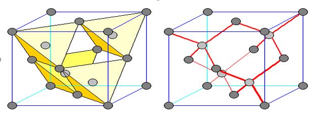
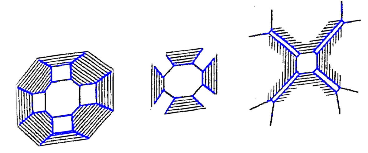
Le dendriti sono strutture ad albero che si formano durante la solidificazione delle leghe metalliche. Il metallo forma cristalli che si accrescono e solidificano nelle direzioni cristallografiche energeticamente più favorevoli. Con un raffreddamento rapido l’accrescimento delle dendriti è limitato. Mentre con un raffreddamento lento si ottengono delle dendriti di dimensioni maggiori, nei casi peggiori visibili a occhio nudo nella zona del ritiro volumetrico.

Figura 3 – Rappresentazione struttura di accrescimento dendritica in una lega

La contrazione volumetrica è intrinseca al processo di solidificazione e, quindi, la porosità da ritiro è una difettosità inevitabile nel processo di fusione.
La porosità da ritiro non può essere eliminata, ma può essere veicolata in punti strategici promuovendo la solidificazione direzionale.

Nella solidificazione di una lega metallica, l’ultimo volume a solidificare, ovvero quello che rimane “caldo” per più tempo, sarà quello che conterrà le porosità da ritiro.
Nella progettazione di un sistema di colata è fondamentale, quindi, lo studio dei fattori termodinamici che portano ad una solidificazione controllata: i canali di colata, gli alimentatori e le materozze vanno studiati e dimensionati in maniera tale da riuscire ad alimentare correttamente il pezzo da realizzare e allo stesso tempo “trattenere” il ritiro fuori dalle zone di interesse.

Per studiare la solidificazione degli oggetti microfusi è importante considerare il modulo di raffreddamento.
Il modulo di raffreddamento, o modulo termico, è dato da rapporto tra massa e superficie di un oggetto M=V/S. A parità di volume, se la superficie dell’oggetto è maggiore, il tempo di solidificazione diminuisce drasticamente. Il tempo di solidificazione è una funzione di M, e dipende anche dal tipo di materiale e dalla geometria dell’oggetto. Studiare il tempo di solidificazione è fondamentale per veicolare la direzione di solidificazione.

Prendiamo ad esempio un oggetto molto semplice, come può essere una fede.
Avendo una geometria circolare e simmetrica il punto in cui andremo a mettere l’alimentatore non ha importanza. Ha importanza, però, la sezione e la geometria di quest’ultimo. Di seguito sono riportati come esempio le simulazioni della solidificazione della stessa fede ma con tre alimentatori a sezione crescente.

Figura 4 – analisi solidificazione della fede nei tre casi studio

Come si può vedere nell’ultima immagine, l’alimentatore con sezione maggiore e rastremato verso la sezione di imbocco del metallo è quello che consente il corretto riempimento del getto e la solidificazione direzionale della fede.

A riprova della correttezza della progettazione dell’alimentatore 3 possiamo vedere, sempre dalla simulazione, la riduzione di porosità (in viola) nell’ultima immagine.

Figura 5 – porosità nelle fedi con alimentatore a sezione crescente

Prendiamo ora ad esempio un’altra geometria semplice di un anello, ma stavolta con sezione variabile.

Figura 6 – anello a sezione variabile

In questo caso, essendo la geometria non simmetrica, il punto in cui andremo ad alimentare l’anello è di fondamentale importanza. Di seguito vediamo nella fig 5 l’andamento della solidificazione a seconda del punto dove si è scelto di mettere l’alimentazione del getto.

Figura 7 – solidificazione dell’anello con alimentazione in punto A o in punto B

La solidificazione osservata nella figura precedente, conduce alla presenza di porosità nelle zone evidenziate nella figura 6.

Figura 8 – evidenza delle porosità da ritiro rilevate dopo simulazione anello con alimentazione in punto A o in punto B

I risultati possono essere verificati osservando i componenti fusi. E’ molto importante, nell’utilizzo dei software di simulazione, tarare l’affidabilità del software con il proprio processo di fusione.
Di seguito sono riportate le immagini delle superfici dell’anello analizzato e fuso con i due diversi posizionamenti dell’alimentatore:

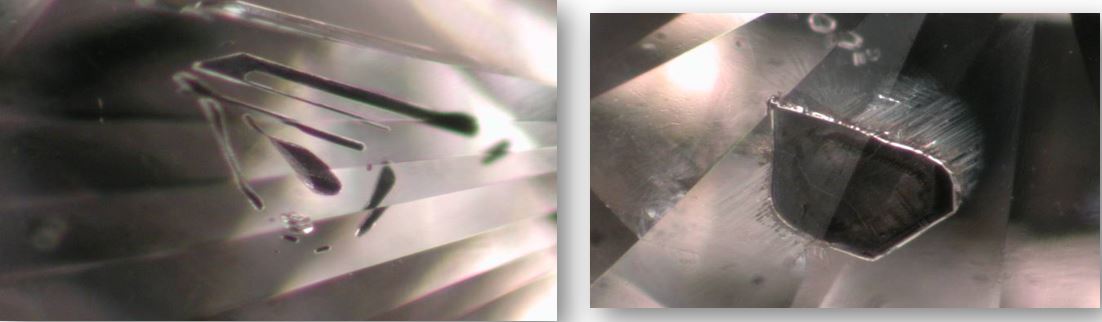
Figura 9 – porosità visibile su anello grezzo di fusione. A sx anello con alimentazione A e a dx anello con alimentazione B

Figura 10 – evidenza di un poro macroscopico sulla superficie dell’anello con alimentazione B

Figura 11 – due fedi lucidate. In evidenza sulla destra porosità da ritiro su pezzo fuso con alimentazione B

Allo stesso modo prendendo in esame un oggetto di dimensioni maggiori, possiamo vedere che le stesse regole della solidificazione direzionale sono applicabili anche in questo caso.
La figura in esame è una “C” che potrebbe essere utilizzata per realizzare la metà di un bracciale.

Figura 12 – geometria a “C” per realizzazione bracciali

Nel primo esempio prendiamo in considerazione il pezzo con la stessa tipologia di alimentazione ma fuso con parametri diversi. In particolare si può notare la variazione di risposta al variare della temperatura, sia di stampo che di fusione.

Figura 13- solidificazione – a sx Tcil:Tc1 Tfus:Tf1 ; a dx Tcil:Tc2 Tfus:Tf2 (con Tc2>Tc1 e Tf2>Tf1)

Figura 14 – porosità – a sx Tcil:Tc1 Tfus:Tf1 ; a dx Tcil:Tc2 Tfus:Tf2 (con Tc2>Tc1 e Tf2>Tf1)

Come si può notare dalle immagini, al crescere della temperatura le dimensioni delle porosità decrescono. Questo avviene perché si da più tempo al metallo per solidificare in maniera direzionale. In questo caso, tuttavia, il solo variare dei parametri di processo non riesce a risolvere il problema alla radice.
È necessario, quindi, modificare l’alimentazione. Prendiamo in esame due tipologie di alimentazioni.

Figura 15 – alimentazione A – alimentazione B

Di seguito possiamo vedere la simulazione del processo di solidificazione in entrambi casi.

Figura 16 – solidificazione bracciale nel caso di alimentazione A (sx) o B (dx)

Analizzando la figura a sinistra si può notare che i sei raggi di alimentazione stanno solidificando prima che il bracciale sia esso stesso solidificato (come nell’esempio precedente), “chiudendo” le strade al metallo per continuare ad alimentare correttamente il pezzo. Nella figura a destra, invece, si nota come i quattro raggi vadano ad alimentare bene il pazzo consentendo una solidificazione direzionale verso il cuore del piantone.

Figura 17 – analisi delle porosità nei due casi di alimentazione A o B

La riprova dell’efficienza dell’alimentazione tipo B è data dall’analisi delle porosità.
In figura 16 si può notare come nel caso B il pezzo sia esente da porosità, mentre nel caso A si riscontrino sei nuclei di porosità da ritiro esattamente dove il metallo ha raffreddato per ultimo sul pezzo.

Le evidenze di queste simulazioni sono riportate nelle immagini seguenti.


Figura 18 – bracciali grezzi di fusione: a sx alimentazione A, a dx alimentazione B

Figura 19 – particolare che mostra porosità da ritiro già dal grezzo sul bracciale con alimentazione A

Figura 19 – a sx bracciale con alimentazione A a dx alimentazione B

L’analisi di queste geometrie semplici dimostra la validità della simulazione. Il software è in grado di prevedere con precisione quali saranno le zone affette da difetti e l’entità di questi ultimi.
La simulazione del processo di microfusione è uno strumento utile al tecnologo che non elimina del tutto il processo di “Trial and Error” ma lo limita all’ambiente virtuale della simulazione abbattendo i tempi e i costi dell’industrializzazione del prodotto.

Tabella 1 – vantaggi simulazione calcolati su casi reali di studio

Lo strumento fondamentale per l’utilizzo del software di simulazione di colata è la modellazione CAD 3D.
Come si è già detto, infatti, per poter simulare il processo di colata è indispensabile partire da un modello 3D, sia del sistema di colata che vogliamo simulare sia dello stampo all’interno del quale andremo a colare il metallo.
Quanto più è accurato il modello di partenza, tanto più saranno accurati i risultati della simulazione.
La modellazione CAD offre anche il vantaggio di poter disegnare e simulare in tempi rapidi diverse tipologie di alimentazioni e di sistemi di colata.
Simulando diverse alimentazioni potremmo stabilire la più idonea al nostro particolare.
Prevedendo la simulazione di colata all’inizio del processo di progettazione, sarebbe possibile individuare da subito eventuali errori di design e intervenire modificando la geometria del modello.
Laddove non è possibile modificare il design del pezzo, si dovrà forzatamente andare ad agire su altri parametri (alimentazioni, parametri di processo, etc..) 

Una volta capita l’importanza della simulazione sul singolo particolare, è possibile esplorare nuove possibilità per sistemi di colata complessi.
Simulare un intero albero di fusione consente, ad esempio, di analizzare il processo nel suo insieme e di ottimizzarlo.

Figura 20 -simulazione colata di un alberello

Concludendo l’introduzione di questa tecnologia nella filiera della creazione orafa è senza dubbio di aiuto alla transizione verso una produzione più performante e mette il “turbo” alle aziende che vogliono impiegare forze e mezzi per implementarla nei loro processi produttivi.

Per poter sfruttare al meglio questa tecnologia occorrono mezzi e studio, tuttavia i vantaggi risultanti dal suo utilizzo (il risparmio di tempo, mezzi e l’efficacia dei risultati ottenuti) abbattono tutte le incertezze. Nel tempo questo diventerà l’unico modo di procedere per industrializzare un manufatto orafo, così come già avviene in tutti gli altri settori di produzione.


Continue reading